A comprehensive guide.
Background lore
You may have seen my other blog post about USB Samurai, linked here. In that post, I described my attempt
at creating a malicious RF controlled USB cable following this blog by Luca Bongiorni. Go give it a read
if you are interested in being taken on an emotional rollercoaster.
Anyway, I am very happy to report that I did indeed reattempt the
project—this time, with extremely successful results!! In this blog,
I will try my best to detail the steps I took this time around, and
hopefully act as a resource for anyone who is interested in pursuing
the same project.
The ingredients to the secret sauce
Before diving into the process of building our cable, we must first understand a little more
about wireless dongles and our objective. The premise of how this tool works is that we, as the attacker, are
disguising ourselves as a Logitech keyboard, sending malicious payloads
to our USB cable containing a receiver as keystrokes. The concept could
be difficult to grasp on paper, so here is a simple diagram of what is happening.
When you interact with a wireless input device, it sends your input as radio packets to its receiver dongle.

The dongle then translates that input and sends it to the computer into human interface device packets.
The source of the packets sent is irrelevant to the computer.
This is important to note as it makes detection of our exploit near impossible.
Notice how there is no physical connection between the attacker and the target? 10/10 stealth mode activated >:)
Hardware
All the physical tinkering we will be doing will be to make the malicious
USB cable. The goal is to deconstruct the cable, solder on a Logitech
Unifying dongle, and then reconstruct the cable, maintaining its full
functionality so that it does not raise any suspicions.

The hardware components we will need for this project are:
- Logitech Unifying dongle
- cheap USB cable of choice
- RF dongle
Some helpful tools are:
- Soldering iron (REQUIRED)
- Flux (Highly recommended)
- XACT-O knife (or other sharp and precise blade)
- Cuticle nipper
- Double-sided mounting tape/small clamps
- Tape
- Superglue
For the Unifying dongle, I followed Luca’s advice and purchased the C-U0012 model,
as it is not only quicker but supports encrypted traffic. As for the RF dongle, I
decided to go with the MakerDiary nRF52840 dongle, as it is supported by LOGITacker
and is readily available on Amazon.
As for tools, my soldering iron of choice was the PINECIL (shoutout to my friend Sam
who recommended it to me a while back). A ton of cool features at a very affordable
price—highly recommend it if you are in the market for a soldering iron. Next, a fresh
XACT-O knife was extremely helpful in slicing open the USB cable as cleanly as possible.
However, there are times when a little more leverage is necessary. That’s where the cuticle
nipper comes in. Trust me, you will thank me later. Finally, some clamps would be extremely
helpful to hold down your components when soldering. I unfortunately did not have any so I
had to get creative with some double-sided mounting tape—which worked like a charm!
Software
There are quite a few tools that we will be using to flash and communicate with our USB cable:
- munifying
- Lightspeed firmware (or whatever your Unifying receiver supports)
- LOGITacker
- PuTTY (or other serial console software)
Huge shoutout to Marcus Mengs and Rogan Dawes for their incredible work on LOGITacker and munifying. This project would not be possible without them.
Checking your equipment
One thing I wish I did the first time around was just testing each individual component prior
to getting my hands dirty with making the physical cable. There were so many points of failure
on the software end that only amplified when I added the uncertainty of hardware I tampered with
to the equation.
Munifying and “receiver” dongle
VM Troubleshooting
Some steps that can be done before busting out your soldering iron include flashing your “receiver”
dongle with the latest supported Unifying firmware. To do this, we will need to use munifying. I
highly recommend interacting with your dongle within a Linux VM of choice (I used Kali). The munifying
software only recognizes the very first dongle it picks up, so having the freedom to manage the devices
you are interacting with virtually is very convenient. Plus, during my first attempt, I was struggling
endlessly to get munifying to recognize my dongle via WSL (I go into more detail in my first USB Samurai
post). Just save yourself the trouble and go with the tried and true method. Trust me.
You may encounter some issues when you first try to get your VM to recognize your dongle (at least, I had
this issue using VMWare). I was digging around to see if anyone else had the same issue, when I stumbled
upon this post
by LuemmelSec. Thankfully, they were able to find the solution in this VMWare doc. To directly
connect USB devices to your VM, you will need to edit your VM’s .vmx file to include the following lines:
usb.generic.allowHID = "TRUE"
usb.generic.allowLastHID = "TRUE"
When you power your machine back on, you should be able to see a list of USB devices that you can manage.
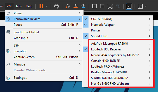
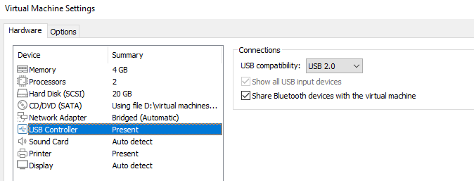
If you are still having issues with getting your VM to recognize your dongle, it may be because “Show all USB
input devices” or “Share Bluetooth devices with the virtual machine” are unchecked in your VM settings. To fix
this, simply power off your VM → open Virtual Machine Settings → USB Controller → make sure both options are
selected.
Munifying setup
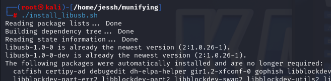
Installing munifying is relatively simple, but I’ll try my best to outline some points of failure that you may
encounter during this process. First, in the home directory of the project, run ./install_libusb.sh
Now, run go build

If you run into issues during this step, you might not have Go installed. Run sudo apt install -y golang
and add the following lines to your .bashrc file.
export GOROOT=/usr/lib/go
export GOPATH=$HOME/go
export PATH=$GOPATH/bin:$GOROOT/bin:$PATH
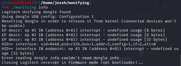
Now, with your Unifying dongle plugged in (don’t forget to connect it to your VM), run ./munifying info to make sure
your dongle is being recognized. If this step is successful, you should see something like this:
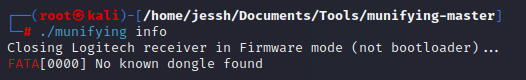
If you are sure you did everything right but are met with this sad sight, make sure you are running munifying as root.
Don’t be discouraged if you are still met with errors during this step. Disconnect and reconnect your dongle or even reseat it
and give it another shot. These things can be finicky at times—you will get it if you did everything right so far!
Now with munifying working properly, we can get our dongle flashed with the latest Lightspeed (or whatever is compatible with your
dongle) firmware. You can find this firmware on Logitech’s Github. We can flash our dongle by running:
./munifying flash -f [firmware file]

Now, run ./munifying info again to make sure the device has been flashed successfully.

LOGITacker and "sender" dongle
As for the “sender” dongle, we will first need to flash it with the appropriate LOGITacker firmware. Each supported dongle along
with their corresponding firmware and flashing instructions can be found in section 2 of the LOGITacker readme. Once you’ve
identified your dongle, grab the firmware here and flash it.
For my MakerDiary dongle, all I had to do was hold down the small black button while I plugged it into my pc and watch for the
flashing red light. Then, I dragged the firmware file onto it, flashing the device.

Once you’ve flashed your dongle successfully, open up PuTTY and connect to it! Below are the configurations I used for my dongle, but yours may vary depending on your hardware.
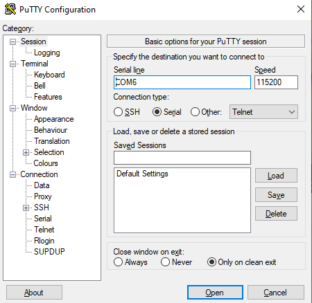
The LOGITacker readme also includes a link to the appropriate terminal settings for each dongle. There, you should be able to find
the appropriate baud rate and other information regarding your dongle.
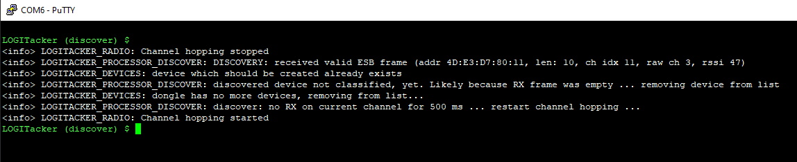
With the proper settings configured, launch your terminal and confirm that you have connected successfully. Don’t forget to hit “return”
a couple times on your keyboard!
Pairing the two devices
Now that you have confirmed that both the “sender” and “receiver” dongles are working properly, you can proceed with the final check–pairing the devices. To do so, you will need to be interacting with each device on isolated environments. For me, I had my Unifying dongle connected to my Kali VM while my MakerDiary dongle was connected to my host. I would highly recommend replicating this set up if possible, as it is tried and true.
Before we move on to the fun stuff, let’s take a moment to understand how the pairing process works.
When the dongle enters pairing mode, it actively listens for requests on the designated pairing address BB:0A:DC:A5:75 for a duration of 30-60 seconds. Upon initial activation, a wireless device typically sends wake-up packets to the dongle. If this fails to establish a connection, the device will proceed to send a pairing request to the fixed address aforementioned. Since these dongles lack firmware support for multiple devices, the first device to respond to the pairing request will be successfully paired. Furthermore, due to limited firmware update capabilities, the pairing process must remain generic to accommodate new devices as well.
A typical pairing exchange consists of the initial pairing request from the device to the dongle, a reply from the dongle to the device that contains the new RF address assigned to the mouse, a payload from the device containing information such as its serial number and USB HID capabilities, a couple more information exchange packets from the dongle to the device, and finally, a confirmation from the device to the dongle.
LOGITacker
The first step to pairing the two devices will be to configure our “sender” dongle with LOGITacker. As my Unifying receiver supports Lightspeed,
I set my LOGITacker dongle to work in Lightspeed mode with options global workmode lightspeed.
You may notice that this CLI does not support backspaces… Tab to complete will be your best friend when interacting with your LOGITacker dongle…
Don’t be like me and spend a majority of my time retyping commands due to typos :(
Now, set it to pairing mode with pair device run.
Munifying
In your Kali VM (or whatever you are running munifying on), with your Unifying dongle connected, run ./munifying unpairall. We do this to
ensure that we can start with a clean slate, as munifying can only support one device at a time. Then, we set it into pairing mode by running
./munifying pair. If you see this:

Congrats! You have successfully paired your devices!
However, more likely than not, your first couple of tries will end up looking more like this:

Troubleshooting
A major pain point in this process is going to be a timing issue. You are going to want to attempt to pair
from munifying as quickly as possible after setting your LOGITacker into pairing mode. To minimize the amount
of time between the two, I pre-ran the two munifying commands so I could just up arrow instead of typing it
all out in the moment. I also split my screen between the PuTTY console and my Kali VM to minimize the
amount of time spent navigating between the two.
Another reason you may not be pairing successfully (assuming you have followed all the steps correctly so far) would
just be because the process tends to be quite finicky. I had to unplug/reconnect my dongles a couple times before I
was able to pair them successfully. Don’t give up!
Saving your dongle
Paired devices are only stored in RAM by default, meaning, each time they are disconnected,
you have to go through the pairing process again. To save your paired device to LOGITacker, run
devices storage save [address] (use tab to autocomplete the address of your receiver dongle but make sure it is correct).
Destruction time: making the cable!
If you want a more detailed walkthrough of the making of the cable, my previous blog goes through every single
road bump and hurdle I encountered on my journey. For this blog, I’ll just briefly go over the steps and any
tips I have for the process.
Step 1: Deconstructing the USB cable
For this step, you will want to run your XACT-O knife down either side of the cable chassis, following the seam
as best as possible. Hopefully, you didn’t purchase a cable with a hard plastic or metal chassis... It’s going
to take quite a few very deep cuts for you to get through the layer of plastic, so approach this step with patience.
When you’re done, you should be left with something that looks like this:

Side note: don’t worry if you cut through the wire in the process. We will be soldering all back together
later anyway. In fact, I would recommend that you cut off the cables if they’re still left intact after
this step so the USB jack is easier to work with.
Now, to access the pins, we will need to snip away the white plastic that they are seated in. This is where
your cuticle nippers shine. Simply bend the pins forward and cut off the exposed plastic. You should be left
with something that looks like this.

Don’t forget to take note of the position of each individual wire during this step. A quick picture right now
will save you a lot of headache when you are soldering later.
There will be plastic projectiles shooting off in random directions at high velocity during this step, so eye
protection is high recommended.
Step 2: Taking the Unifying dongle apart
This step is going to be pretty challenging… At least, it was for me. The goal is to free the internal components
of the receiver from its chassis. Though this was my second attempt, I still have not found any tips or tricks to
make this process easier. My only words of advice would be to be patient. You don’t want to accidentally damage
your dongle in the process.
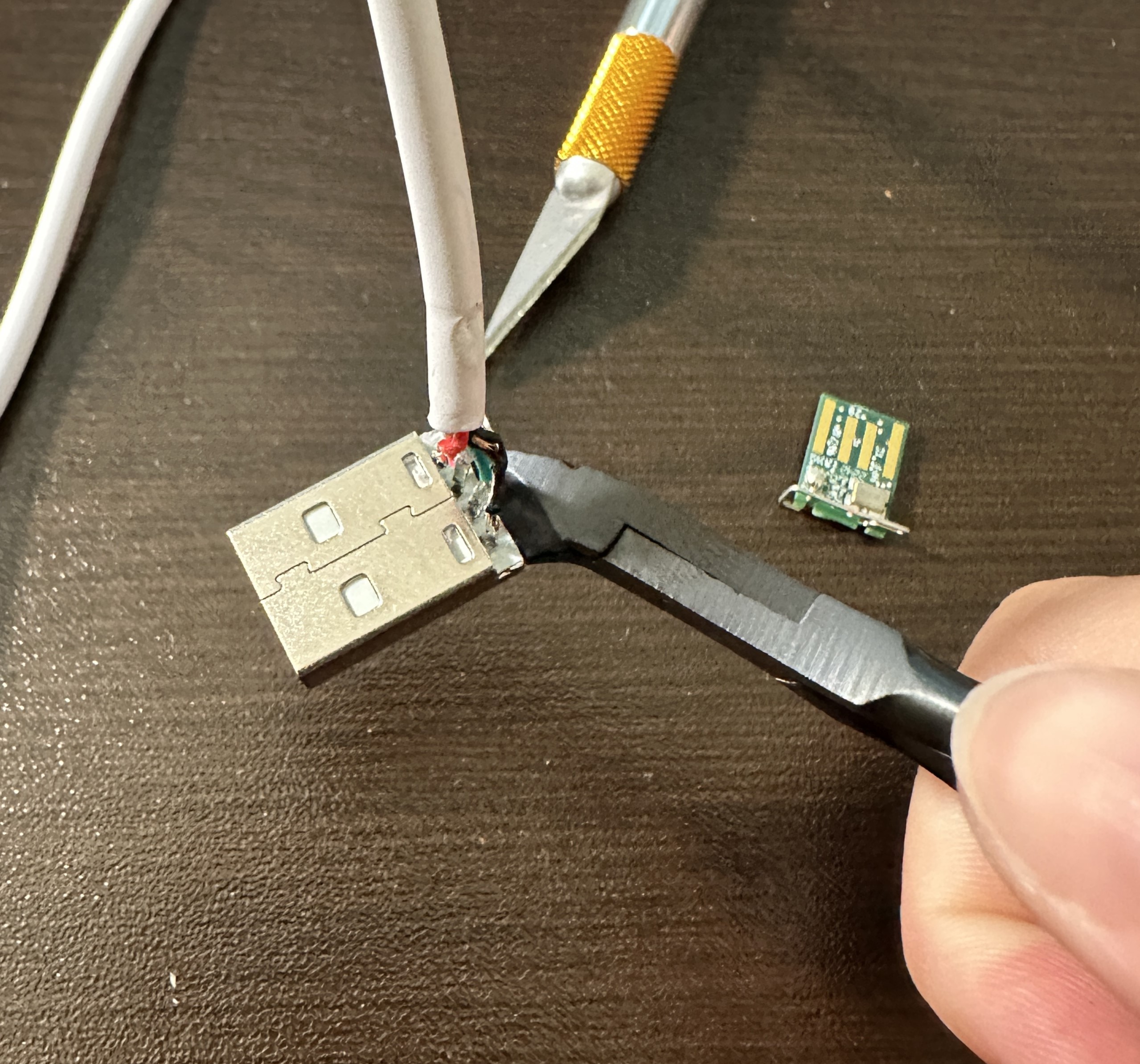
My approach was to shave off as much of the plastic around the dongle with my XACT-O knife, occasionally switching
to my cuticle nippers to pry away at the more difficult bits. When I was left with just the metal connector, I stuck
my XACT-O knife under the connecting part and carefully pried it open. When enough room was created, the dongle inside
could be slipped out with a little help. The aftermath of my destruction looked like this:

Step 3: Preparing the cable
If your cable is not already detached from the USB connector, snip them off as cleanly as you can. Then, strip
off the outer plastic to reveal the individual wires within. Now, carefully, strip off a small segment of the
plastic covering each wire to reveal the bare wire underneath. As I didn’t have wire strippers on hand, I just
used a pair of scissors and carefully made incisions in the plastic without damaging the wire underneath. Of
course, wire strippers would be preferred, but scissors could do the job just fine.
With the metal wires exposed, twist them tight and dip them in flux to prepare them for soldering. Set the cable aside for later.
Step 4: Soldering everything together
For this step, I decided to change my approach from my last attempt. Instead of pressing the dongle and USB
connector together and applying solder, I applied a little bit of solder to the dongle and USB connector
individually first. Flux is going to be your best friend for this part of the process. Don’t be shy and load
it up. Pro tip: secure your components using double-sided mounting tape before soldering.
When the solder is cooled, press your USB connector onto your dongle (hopefully secured in place) and apply
heat to the pins using your soldering iron to melt the solder together. Here is a picture of the correct
orientation of each component for reference:

Hold the connector down as the solder cools. It may get a little hot, but it is essential that the pins solidify
onto their corresponding positions properly. This will save you a lot of trouble down the line.
With your components soldered together, we can prepare the cable to be soldered back on as well. Split apart each wire
to allow yourself enough room to work with them individually. Make sure each wire is loaded up with flux before proceeding
to the next step, as you are going to have to act pretty quickly.
With your cable secured with a clip (or help from a friend–shoutout to Evan), load up your soldering iron with a little bead
of solder. Then, with the solder loaded on, press the tip of your iron to your exposed wire. The flux should allow the metal
to form an even coating over the wire. Do this for each individual wire.
Reapply flux to each wire and your dongle. Now, with your dongle secured and your wires covered in solder and flux,
hold each wire to its corresponding pin and apply heat from your soldering iron. This is where the picture you
took when you deconstructed the cable comes in. Make sure you solder each wire back properly.
During this step, I accidentally created a solder bridge between two of my pins as I got a little too excited
with the solder. To avoid this, just remember that less is more when soldering your wires. You can always apply
more solder if necessary, but removing extra solder is a lot more challenging. I fixed my issue by putting a ton
of flux in the affected area and repeatedly parting the solder with my iron. Thankfully, that was sufficient to
fix the issue.
Step 5: Reassembling the cable
Almost there!! All that’s left is to stuff this modified cable back into its chassis. As expected, the process is not
as simple as covering the cable back up with the plastic, as our cable is a lot bulkier now. You may have to carve
out some of the plastic from your chassis to make room for the altered components. The cuticle nippers are very
helpful during this step as well!
I would not recommend sealing your cable back up using super glue, or anything permanent, during this initial attempt.
Securing the cable with something less permanent like tape allows you to take it apart and fix any issues if your cable
isn’t working properly after the modifications.
Once you have confirmed that your cable works properly, you can go back and secure it with something more permanent.
The fun stuff
Now with your cable all ready to go, hold your breath as you plug it in for the first time. If it gets recognized by
your operating system, WOOHOO!! You did it!! …kinda xP You should still test it with munifying by running ./munifying info.
Don’t freak out if it doesn’t work on the first try–this stuff is pretty finicky, remember? Reseat the cable and try again.
If you are able to get the cable recognized by munifying, CONGRATULATIONS!! We can move on to the fun stuff now! >:)
Since we already flashed all our components and saved our pairing configuration prior to constructing the cable, all we have to do
on the receiver dongle end of things is to plug it in (don’t forget to connect it to your VM). As for LOGITacker, we will have to
initiate the connection before we can interact with our receiver. To do so, first run devices storage load [address]
We also want to make sure the dongle is in Lightspeed mode, just in case with options global workmode lightspeed.
Now, we want to write a quick script to inject so we can verify that everything is working properly. We can create a
script using the script command. Here is a quick example that you can use:
script clear
script string whoami
script delay 500
script press ENTER
We can save the script by running script store whoami
Confirm that the script is saved with script list and display the contents of the script by running script show [name].
Now, we can specify our target by running inject target [address].
Load your script with script load [name].
Send it off with inject execute!
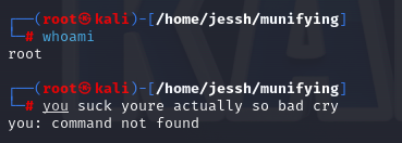
If all goes well, you should see your script being run on your Kali VM.
Some ideas for devious use cases...
Conclusion
Well, hope you had fun and learned something, whether you were just reading this blog out of curiosity, or actually following along because you wanted a little deviousness in your life. Either way, thank you for reading to the end and feel free to contact me with any questions you may have at jess@jessicacleung. I can’t guarantee that I will be of much help, but I will try my best!